Org.simantics.diagram: Difference between revisions
| Line 25: | Line 25: | ||
This section describes how diagrams are modelled in the semantic graph using [[Graphical ontology notation]]. | This section describes how diagrams are modelled in the semantic graph using [[Graphical ontology notation]]. | ||
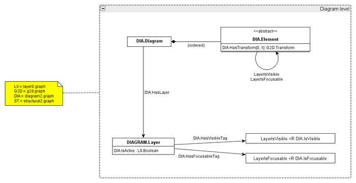
[[Image:diagrams.png|700px|none|thumb|The diagram level model containing diagrams, layers and diagram elements. ([[Image:diagrams.graphml|image source]])]] | [[Image:diagrams.png|700px|none|thumb|The diagram level model containing diagrams, layers and diagram elements. ([[:Image:diagrams.graphml|image source]])]] | ||
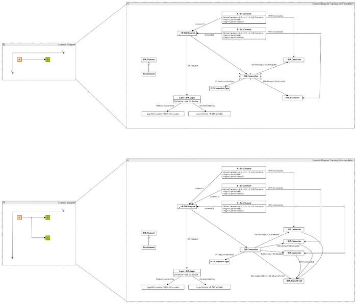
[[Image:diagram_topology.png|700px|none|thumb|Example diagrams showing diagram models for simple and branched diagram topologies. ([[Image:diagram_topology.graphml|image source]])]] | [[Image:diagram_topology.png|700px|none|thumb|Example diagrams showing diagram models for simple and branched diagram topologies. ([[:Image:diagram_topology.graphml|image source]])]] | ||
== How It Works == | == How It Works == | ||
Revision as of 09:36, 13 October 2010
org.simantics.diagram (SVN) offers basic support for diagramming based on the graph database.
Features
- Graph-based diagram persistence and synchronization
- Offers:
- graph → diagram model loading and change tracking
- persisting of diagram changes back to the graph
- Diagram editor base for Eclipse RCP
- Contains a basic example diagram editor for the Eclipse Workbench.
- Symbol Library
- Provides a symbol library Eclipse View based on SWT and org.simantics.g2d.
Diagrams
Data Model
This section describes different models used to represent diagrams both during runtime and in persistent storage.
Runtime
TODO: describe how diagrams are represented in the 2D/Diagram runtime model defined in svn:2d/trunk/org.simantics.g2d/src/org/simantics/g2d/diagram.
Graph Data Model
This section describes how diagrams are modelled in the semantic graph using Graphical ontology notation.


How It Works

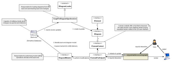
The canvas context has its own thread which is used for manipulation of the context. Diagrams are specified to be single-threaded. The canvas context's thread shall also be used for manipulating the diagram after it is assigned to the context.
The diagram's DiagramClass should contain a TransactionContext handler. The transaction context contains a mechanism for readers-writers locking which should be used for synchronizing the use of DiagramMutator. GraphToDiagramSynchronizer uses the TransactionContext with read-locking to prevent race-conditions between itself and DiagramMutator users. Participants generally do something like this: <source lang="java">
   final DiagramMutator mutator = diagram.getHint(DiagramHints.KEY_MUTATOR);
   DiagramUtils.inDiagramTransaction(diagram, TransactionType.WRITE, new Runnable() {
       @Override
       public void run() {
           // Perform mutator operations...
           mutator.commit();
       }
   });
</source>
If all you need to do is to synchronize a set of elements into the backend, a shorter version is to use one of: <source lang="java"> public class DiagramUtils {
public static void synchronizeHintsToBackend(IDiagram diagram, final IElement... elements) { ... }
public static void synchronizeHintsToBackend(IDiagram diagram, final Collection<IElement> elements) { ... }
} </source>
Development
TODO: intro
Interfaces
An interface for loading an IDiagram from the graph. GraphToDiagramSynchronizer is a concrete implementation of this.
This factory is used for two things:
1. loading an ElementClass from an DIAGRAM.Element type resource in the graph.
2. loading IElement instances from DIAGRAM.Element instance resources in the graph.
Essentially the factory does two things:
- create ElementClass for DIAGRAM.Element resources
- load the data (hints) of a diagram element according to the graph database properties
To make use of your own factory, just make your element types and instances adaptable to this interface through Resource Adaptation.
See the source file for a description.
An interface that an element instance must be adaptable to through Resource Adaptation if it needs to do any custom writing to add or remove itself to/from the graph database. In this case custom means anything else besides the plain old HasTransform property.
A hint synchronizer is responsible for reflecting the hint values of an element into the back-end system. GraphElementFactory implementations are responsible for setting the synchronizer in elements if necessary using the SynchronizationHints.HINT_SYNCHRONIZER key.
Loading a diagram
<source lang="java">
   IDiagram loadDiagram(final ICanvasContext canvasContext, RequestProcessor processor, Resource diagramResource,
           ResourceArray structuralPath) throws DatabaseException {
       GraphToDiagramSynchronizer synchronizer = processor.syncRequest(new Read<GraphToDiagramSynchronizer>() {
           public GraphToDiagramSynchronizer perform(ReadGraph graph) throws DatabaseException {
               return new GraphToDiagramSynchronizer(graph, canvasContext, createElementClassProvider(graph));
           }
       });
       IDiagram d = requestProcessor.syncRequest(new DiagramLoadQuery(diagramResource, structuralPath, synchronizer, null));
       return d;
   }

   protected IElementClassProvider createElementClassProvider(ReadGraph graph) {
       DiagramResource dr = DiagramResource.getInstance(graph);
       return ElementClassProviders.mappedProvider(
               ElementClasses.CONNECTION, DefaultConnectionClassFactory.CLASS.newClassWith(new ResourceAdapterImpl(dr.Connection)),
               ElementClasses.FLAG, FlagClassFactory.createFlagClass(dr.Flag)
       );
    }
</source>
Creating new element types
To create new element types (classes) and to load them into a diagram from the graph, the following is needed:
- Define the new element types in your own ontology. New elements must extend DIAGRAM.Element.
- Define resource adapters for:
- defining an ElementClass for your element type
- loading your element instances (IElement) from the graph database
- possible custom logic for adding/removing your element type instances to/from the graph database. This is needed if your element has other properties to be synchronized besides an affine transformation.
Example
Define the adapters:
<source lang="xml"> <?xml version="1.0" encoding="UTF-8"?> <adapters> <target interface="org.simantics.diagram.adapter.ElementFactory"> <resource uri="http://www.example.org/MyOntology#MyElement" class="org.example.elements.MyElementFactory" /> </target>
<target interface="org.simantics.diagram.adapter.ElementFactory"> <type uri="http://www.example.org/MyOntology#MyElement" class="org.example.elements.MyElementFactory" /> </target>
<target interface="org.simantics.diagram.synchronization.graph.ElementWriter"> <resource uri="http://www.example.org/MyOntology#MyElement" class="org.example.elements.MyElementWriter" /> </target> </adapters> </source>
Define the adapter classes:
<source lang="java"> public class MyElementFactory implements ElementFactory {
...
}
public class MyElementWriter implements ElementWriter {
...
} </source>
Note that for easier implementation of ElementFactory, you can and should extend SyncElementFactory or at least ElementFactoryAdapter.
Creating new connection types
To create new element types (classes) and to load them into a diagram from the graph, the following is needed:
- Define the new element types in your own ontology. New elements must extend DIAGRAM.Connection.
- Define resource adapters for:
- defining an ElementClass for your connections
The current diagramming system is fixed to having connections the format defined in UC:Branch Connection#Changes_for_branching. The logic of loading connections from the graph is also currently hardcoded in GraphToDiagramSynchronizer. Summa summarum, only ElementClass aspects of connections can currently be customized.
The customizable aspects of a connection are:
- The general appearance of a connection is defined per-connection by a STRUCTURAL.HasConnectionType property attached to a DIAGRAM.Connection instance.
- The used routing algorithm is defined by DIAGRAM.HasRouting tags in DIAGRAM.Connection instance.
- A custom inherited DIA.Connection type can be used to customize the ElementClass and loading of corresponding connection elements. Basically this allows customization of all visual/interactive aspects of connection elements.
- Statically defining start and end arrows for element terminal connectors via EdgeVisualsConfigurer and resource adapters:
<source lang="xml"> <?xml version="1.0" encoding="UTF-8"?> <adapters>
       <target interface="org.simantics.g2d.connection.EdgeVisualsConfigurer">
               <baseType uri="http://www.simantics.org/Diagram-2.0/HasConnector" />
               <resource uri="http://www.simantics.org/Diagram-2.0/HasPlainConnector"
                         class="org.simantics.diagram.content.ArrowConfigurer">
                       <string>none 0</string>
               </resource>
               <resource uri="http://www.simantics.org/Diagram-2.0/HasArrowConnector"
                         class="org.simantics.diagram.content.ArrowConfigurer">
                       <string>fill 1</string>
               </resource>
       </target>
</adapters> </source>
Example
Define the adapters:
<source lang="xml"> <?xml version="1.0" encoding="UTF-8"?> <adapters> <target interface="org.simantics.diagram.adapter.ElementFactory"> <type uri="http://www.example.org/MyOntology#MyConnection"
class="org.example.connections.ConnectionClassFactory" />
<resource uri="http://www.example.org/MyOntology#MyConnection" class="org.example.connections.ConnectionEdgeClassFactory" /> </target> </adapters> </source>
Visual properties can be specified for connection instances using the STRUCTURAL.HasConnectionType relation to a STRUCTURAL.ConnectionType instance.
<source lang="python">
TODO: explain HasConnectionType
</source>
Supporting Copy-Paste
To support copy paste operations in the diagram, there's a generic diagram participant called CopyPasteHandler. Adding the participant to your canvas context will make your canvas able to handle CUT/COPY/PASTE commands. To provide your domain-specific logic for actually performing the copy operation in the back-end (e.g. graph database), you need to attach a CopyAdvisor to your diagram using the COPY_ADVISOR hint. Note that this means that back-end support for copy-paste is diagram/diagram editor -specific, not element-specific.
See interface CopyAdvisor and its implementation(s):
- ChainedCopyAdvisor - Simple CopyAdvisor proxy implementation. Takes another advisor and forwards all calls to it.
Not contained in org.simantics.diagram but in org.simantics.modeling are two implementations that provide proper support for copying structural components:
- ComponentCopyAdvisor - A primitive advisor for copying structural component instances.
- MappedElementCopyAdvisor - A proxy advisor that
- copies a diagram element
- if the parameter element has a a structural component mapped to the copied element (with relation MODELING.ElementToComponent) it calls the proxied advisor which can be e.g. ComponentCopyAdvisor.
Example
<source lang="java">
   /**
    * Setup a copy advisor that primarily copies diagram elements
    * and secondarily components possibly mapped to them.
    */
   void addCopyPasteSupport(ICanvasContext ctx, IActionBars actionBars) {
       ctx.add( new CopyPasteHandler( actionBars.getStatusLineManager() ) );
   }
   /**
    * Setup a copy advisor that primarily copies diagram elements
    * and secondarily components possibly mapped to them.
    */
   void setupCopyAdvisor(IDiagram diagram) {
       diagram.setHint(SynchronizationHints.COPY_ADVISOR, new MappedElementCopyAdvisor(new ComponentCopyAdvisor()));
   }
</source>
Symbol Library

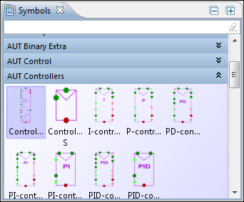
The symbol library (SVN) is an Eclipse Workbench ViewPart that shows a set of grouped modelling symbols to the user. The groups are implemented using the Eclipse Nebula PGroup custom SWT widget. The groups show their contained symbols when expanded by clicking the group caption.
The symbols can be selected and dragged on to diagrams to instantiate them as part of your models.
Development
Concepts
There are only a few key concepts (interfaces) which are used for populating the symbol library view. Each interface is very simple and data source independent.
- Symbol Group
- A composition of symbol items. See interface ISymbolGroup.
- Symbol Item
- A single symbol that
- has a name
- belongs to some symbol group
- can render itself, using the Image interface
- See interface ISymbolItem.
- Symbol Manager
- (DEPRECATED) For managing the available symbol groups within an active project. See interface ISymbolManager.
- Symbol Group Provider
- A very simple provider for symbol groups that does not have listening capabilities. See interface ISymbolGroupProvider. In order to contribute symbol groups into the symbol library there's no absolute must to use or implement this interface - using Symbol Manager is enough. The main reason why this interface exists is to enable data-oriented initialization of the symbol library, e.g. based on Resource Adaptation which needs an interface to adapt to that can be used to provide Symbol Groups for the Symbol Manager.
Contributing to the library
In a nutshell, contributing symbols is a matter of modelling contributions in the ontology by attaching symbol contributions to your custom diagram types.
Types and relations to notice:
- DIAGRAM.Diagram
- DIAGRAM.HasSymbolContribution
- DIAGRAM.BasicSymbolContribution
- DIAGRAM.BasicSymbolContributionHasSymbolLibrary
Things to notice
- Symbols must be represented using an ElementClass which needs contain an StaticSymbol ElementHandler.
Download
| Version | Date | SVN |
| unstable | - | svn:2d/trunk/org.simantics.diagram |
| 0.9.2 | svn:2d/tags/0.9.2/org.simantics.diagram | |
| 0.9.1 | svn:2d/tags/0.9.1/org.simantics.diagram | |
| 0.9.0 | 31.12.2009 | svn:2d/tags/0.9.0/org.simantics.diagram |
See Also
Current Development
Plans
Reconnecting
- For selected connections, display 'gizmos' for each edge ending at connector or branch point
- Detect drag events for gizmos
- Detect terminal node while dragging and acquire validation info from server
- At drop initiate element model change