Difference between revisions of "Diagram connections"
m (Created page with '= Orthogonal connections = Definitions: ; Connection : A collection of connection points, route lines and edges (AreConnectedTo) between these. ; Connection point : Attaches the...') |
|||
| Line 57: | Line 57: | ||
User can create new route lines by moving a corner or a line segment with some modifier key pressed. Moving a corner creates two new route points and moving a line segment creates four new route lines. | User can create new route lines by moving a corner or a line segment with some modifier key pressed. Moving a corner creates two new route points and moving a line segment creates four new route lines. | ||
| + | |||
| + | [[Category: Diagram Development]] | ||
Latest revision as of 16:03, 28 January 2011
Orthogonal connections
Definitions:
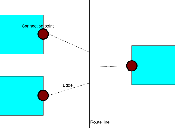
- Connection
- A collection of connection points, route lines and edges (AreConnectedTo) between these.
- Connection point
- Attaches the connection to a terminal of an element. Each connection point has exactly one edge.
- Route line
- Determines how the connection is routed and makes possible to branch the connection. A route line has one or more edges connected to it.
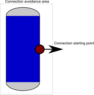
A connection point is defined by the following properties:
- Starting points
- A set of starting point together with initial direction of the connection
- Connection avoidance area
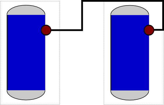
- A rectangle that usually contains all starting points. A connection beginning from the connection point may not turn before leaving the connection avoidance area and it must not intersect the interior of the connection avoidance area after it has left it.
Route lines have the following properties:
- Direction
- Route line is either horizontal or vertical
- Position
- Y coordinate, if vertical, X coordinate if horizontal.
There cannot be an edge between two parallel route lines.
Routing algorithm
A connection is converted to line segments for rendering. Additionally a list of points where three or more edges meet is generated (these may be rendered with small black dots).
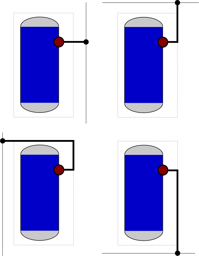
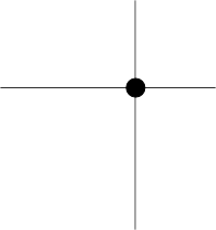
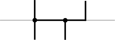
The algorithm maintains a multiset of attachment points for each route line (these are shown as black circles in pictures).
Each edge generates zero or more line segments. There are following cases:
- Edge between two connection points
- Behaves as the currently used routing algorithm. Note that this must be the only edge of the connection.
- Edge between connection point and route line
- Find the shortest possible orthogonal polyline from the connection point to the route line that avoids the connection avoidance area. In some cases there are two different alternatives: postpone these cases and choose later the alternative that makes line segements of the route lines shorter.
- Edge between route lines
- Because one of the route lines is horizontal and other is vertical, they intersect in a unique position. Add this position to the multisets of the route lines.
For each route line, find the extremal attachments points in the multisets. Add line segements between these points and remove points from the multisets (if the multiset contains many copies of the same extremal point, remove the point only once). Now all points left to multisets are points where three or more edges meet.
Editing connection
When the connection is selected, line segments generated by route lines should be rendered differently from the other line segments.
User can move any line segment of the connection. If the line segment was generated by a route line, it is enough to update the route line. Otherwise a route line whose direction corresponds to the direction of the line segment is generated. One additional route line is created if necessary to avoid an edge between parallel route lines. User can also move a corner. In this case the adjacent line segments are if necessary converted to route lines and moved.
User can remove a route line that has at most two edges from context menu (what if this leads to an edge between parallel route points?).
User can create new route lines by moving a corner or a line segment with some modifier key pressed. Moving a corner creates two new route points and moving a line segment creates four new route lines.
